Roger Jones
2012-06-15 16:28:24 UTC
Hi, Vacuumlanders,
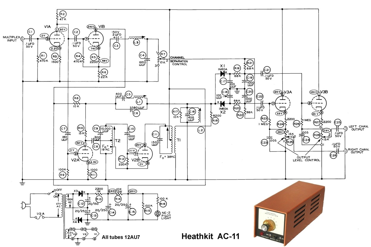
I've just found one of these in some "inherited treasures". It's a
black, oblong box-like thing with three 12AU7's from the chassis
numbers (but there's one 12AT7 in mine at the V2 position.) It looks
very clean and may well be in working condition, but not tried yet.
I've just reformed B+ filter caps for now with the tubes out - caps
seem OK, tubes test good.
Can anyone point me to a schematics for this unit? It's not on the
Heathkit archive that I can access, viz: http://www.vintage-radio.info/heathkit/index.htm
Thanks for all replies,
Cheers,
Roger