N Cook
2007-02-26 10:34:49 UTC
Last time it was used (long ago) it went bang and the owner stored it, so
treading carefully.
Nothing obviously gone bang and cold basic testing the electrolytics and
large Rs seem ok.
Not got to the power devices area yet.
It was correctly altered for use in the UK but ominously a farmyard smell
seems
strongest around the mains transformer, primary seems ok - anyone familiar
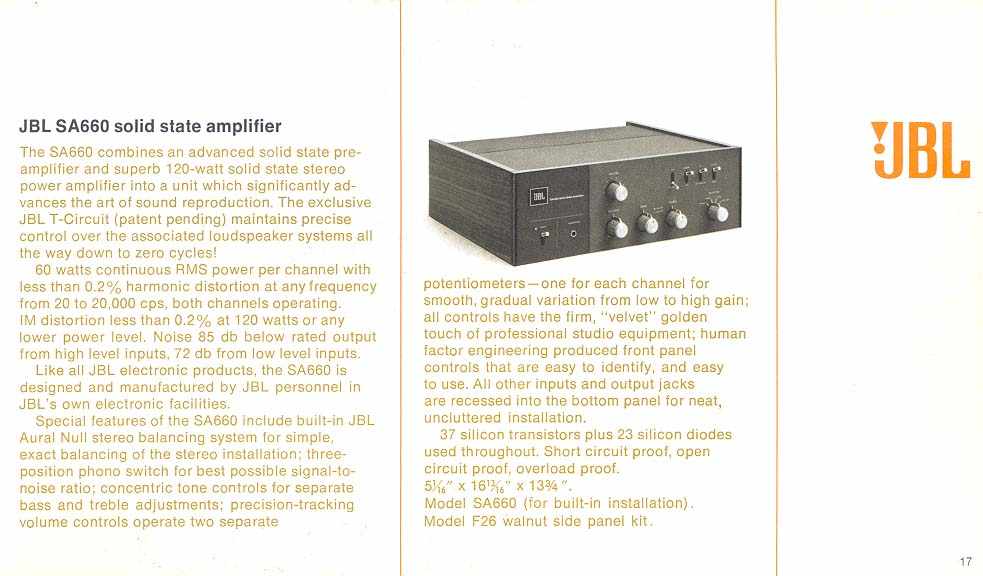
with JBL.
I have the schematic
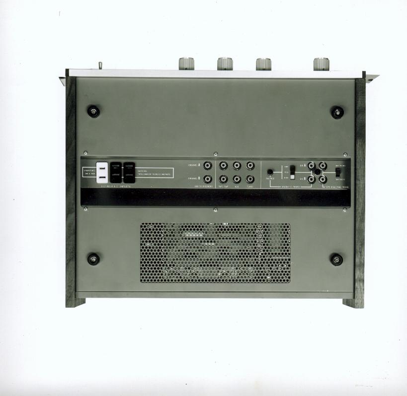
I've now removed the side dished covers to the transformer.
The smell is negligible inside it and nothing charred or smoke stained
inside that I can see, but the two 110V coils measure 4.4ohm and 3.5 ohm .
The failure occured a week after converting the 2 parallel for the USA to
both in series for UK which is another reason for suspecting the
transformer.
But the mains fuse (correctly rated for UK) is still ok.
I'll have to carefully power up via a variac I think
treading carefully.
Nothing obviously gone bang and cold basic testing the electrolytics and
large Rs seem ok.
Not got to the power devices area yet.
It was correctly altered for use in the UK but ominously a farmyard smell
seems
strongest around the mains transformer, primary seems ok - anyone familiar
with JBL.
I have the schematic
I've now removed the side dished covers to the transformer.
The smell is negligible inside it and nothing charred or smoke stained
inside that I can see, but the two 110V coils measure 4.4ohm and 3.5 ohm .
The failure occured a week after converting the 2 parallel for the USA to
both in series for UK which is another reason for suspecting the
transformer.
But the mains fuse (correctly rated for UK) is still ok.
I'll have to carefully power up via a variac I think