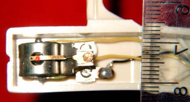
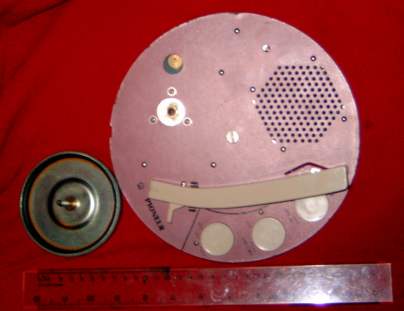
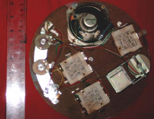
Discussion:
Pioneer Hawaiian , 1960s portable record player
(too old to reply)
N_Cook
2012-09-29 17:56:06 UTC
Permalink
Any technical info anywhere?
pic of similar here,
Loading Image...
Particularly any pickup and speaker info
Not powered up yet, just cold checking at the moment, I'm informed its not
working.
Nothing active inside , 10 ohm resistor , speaker with 2 coils of 36 ohm
each ?
6x 1.5V batteries
Nippon Chemi-con electrolytic 500uF, 6V number on it 056313G , datecode 1963
13/52 ?
hifi-tek
2012-09-29 19:23:23 UTC
Permalink
Post by N_Cook
Any technical info anywhere?
pic of similar here,
http://farm2.staticflickr.com/1267/4701108988_fe2868f377_z.jpg
Particularly any pickup and speaker info
Not powered up yet, just cold checking at the moment, I'm informed its not
working.
Nothing active inside , 10 ohm resistor , speaker with 2 coils of 36 ohm
each ?
6x 1.5V batteries
Nippon Chemi-con electrolytic 500uF, 6V number on it 056313G , datecode 1963
13/52 ?
This is fascinating. Can you show some interior pics? Kinda sketchy info,
no active components at all?
Tom
philo
2012-09-29 20:45:28 UTC
Permalink
Post by N_Cook
Any technical info anywhere?
pic of similar here,
http://farm2.staticflickr.com/1267/4701108988_fe2868f377_z.jpg
Particularly any pickup and speaker info
Not powered up yet, just cold checking at the moment, I'm informed its not
working.
Nothing active inside , 10 ohm resistor , speaker with 2 coils of 36 ohm
each ?
6x 1.5V batteries
Nippon Chemi-con electrolytic 500uF, 6V number on it 056313G , datecode 1963
13/52 ?
This is fascinating. Can you show some interior pics? Kinda sketchy info,
no active components at all?
Tom
Yes I am fascinated too...I think I'd just check the speakers for
continuity then give it a try

My first record player (back around 1955) had no electronics at all.
Just a motor and a tone arm. Kind of a mini Victrola
--
https://www.createspace.com/3707686
hifi-tek
2012-09-29 20:59:40 UTC
Permalink
Post by philo
Post by N_Cook
Any technical info anywhere?
pic of similar here,
http://farm2.staticflickr.com/1267/4701108988_fe2868f377_z.jpg
Particularly any pickup and speaker info
Not powered up yet, just cold checking at the moment, I'm informed its not
working.
Nothing active inside , 10 ohm resistor , speaker with 2 coils of 36 ohm
each ?
6x 1.5V batteries
Nippon Chemi-con electrolytic 500uF, 6V number on it 056313G , datecode 1963
13/52 ?
This is fascinating. Can you show some interior pics? Kinda sketchy info,
no active components at all?
Tom
Yes I am fascinated too...I think I'd just check the speakers for
continuity then give it a try
My first record player (back around 1955) had no electronics at all.
Just a motor and a tone arm. Kind of a mini Victrola
I had a rather unusal portable phono in the early '70's, made by Arvin. It
was battery operated, 6 D cells IIRC, monophonic, but it had a miniature V-M
record changer in it! Very cool to look at, played three speeds, up to 12"
records. Very good centrifugal switch governed motor. Ceramic cart, not so
kind to records, abuout 5-6 grams tracking force. Yard saled it years ago,
kinda regretting that . . .
Tom
philo
2012-09-29 21:02:30 UTC
Permalink
Post by hifi-tek
Post by philo
Post by N_Cook
Any technical info anywhere?
pic of similar here,
http://farm2.staticflickr.com/1267/4701108988_fe2868f377_z.jpg
Particularly any pickup and speaker info
Not powered up yet, just cold checking at the moment, I'm informed its not
working.
Nothing active inside , 10 ohm resistor , speaker with 2 coils of 36 ohm
each ?
6x 1.5V batteries
Nippon Chemi-con electrolytic 500uF, 6V number on it 056313G , datecode 1963
13/52 ?
This is fascinating. Can you show some interior pics? Kinda sketchy info,
no active components at all?
Tom
Yes I am fascinated too...I think I'd just check the speakers for
continuity then give it a try
My first record player (back around 1955) had no electronics at all.
Just a motor and a tone arm. Kind of a mini Victrola
I had a rather unusal portable phono in the early '70's, made by Arvin. It
was battery operated, 6 D cells IIRC, monophonic, but it had a miniature V-M
record changer in it! Very cool to look at, played three speeds, up to 12"
records. Very good centrifugal switch governed motor. Ceramic cart, not so
kind to records, abuout 5-6 grams tracking force. Yard saled it years ago,
kinda regretting that . . .
Tom
I've done much worse.

I actually gave away a Regency TR-1 not having a clue what it was.
I doubt if anyone could make a mistake bigger than that :(
--
https://www.createspace.com/3707686
hifi-tek
2012-09-29 21:08:56 UTC
Permalink
Post by philo
Post by hifi-tek
Post by philo
Post by N_Cook
Any technical info anywhere?
pic of similar here,
http://farm2.staticflickr.com/1267/4701108988_fe2868f377_z.jpg
Particularly any pickup and speaker info
Not powered up yet, just cold checking at the moment, I'm informed its not
working.
Nothing active inside , 10 ohm resistor , speaker with 2 coils of 36 ohm
each ?
6x 1.5V batteries
Nippon Chemi-con electrolytic 500uF, 6V number on it 056313G ,
datecode
1963
13/52 ?
This is fascinating. Can you show some interior pics? Kinda sketchy info,
no active components at all?
Tom
Yes I am fascinated too...I think I'd just check the speakers for
continuity then give it a try
My first record player (back around 1955) had no electronics at all.
Just a motor and a tone arm. Kind of a mini Victrola
I had a rather unusal portable phono in the early '70's, made by Arvin. It
was battery operated, 6 D cells IIRC, monophonic, but it had a miniature V-M
record changer in it! Very cool to look at, played three speeds, up to 12"
records. Very good centrifugal switch governed motor. Ceramic cart, not so
kind to records, abuout 5-6 grams tracking force. Yard saled it years ago,
kinda regretting that . . .
Tom
I've done much worse.
I actually gave away a Regency TR-1 not having a clue what it was.
I doubt if anyone could make a mistake bigger than that :(
Wow, you beat me by a country mile! Sheesh, I don't think I would ever
admit doing that! Those are very collectable, but ya' know, they are just
mediocre radios. Gotta keep telling yourself :-)
philo
2012-09-29 23:04:35 UTC
Permalink
Post by hifi-tek
Post by philo
O
<snip>
Post by hifi-tek
Post by philo
I've done much worse.
I actually gave away a Regency TR-1 not having a clue what it was.
I doubt if anyone could make a mistake bigger than that :(
Wow, you beat me by a country mile! Sheesh, I don't think I would ever
admit doing that! Those are very collectable, but ya' know, they are just
mediocre radios. Gotta keep telling yourself :-)
The only thing that allows me to live with myself is knowing that the
22.5 volt battery clip had been modified. One of the terminals had been
pulled out so the radio could be used with a standard 9v battery. I am
sure the radio would not have full value...but definitely a major error.
Too late now
--
https://www.createspace.com/3707686
N_Cook
2012-09-30 07:51:08 UTC
Permalink
The slide sw in that pic is rotary speed change sw 45,33 and power off on
this one
The pink deck plate is hardboard with the dimpled surface under. The 2 pots
are wire-wound 310R and 42R in circuit.
What I would like to know is what is the cartridge, 3 wires to it, one wire
to battery negative of seriesed 4 making 6V , and only that wire, so the
current of the 6V passes through the cartridge.

The motor is probably from an isolated 3V pair of batteries.
There is a cardboard strobe disc on the platten , for 60Hz countries but it
is now in 50 Hz UK
N_Cook
2012-09-30 10:41:21 UTC
Permalink
pickup, mm scale
Loading Image...

pickup wires now desoldered
Resistance of yellow lines to frame black, wavering around 10K and 50K,
touching the stylus with a few gm of pressure and the resistance changes a
lot.

Speaker frame 77x77mm , marked
Pioneer
B
JGQ

2mm spindle of motor is pivotted to touch inside of "tyre " on inside of the
platten , rubber tyre 87mm internal , 91mm outside.
Speed change by resistanc ein line with the motor
William Sommerwerck
2012-09-30 11:19:12 UTC
Permalink
Post by N_Cook
What I would like to know is what is the cartridge, 3 wires to it,
one wire to battery negative of seriesed 4 making 6V, and only
that wire, so the current of the 6V passes through the cartridge.
This phonograph would likely have used a cheap ceramic pickup, which isn't
connected to a power source.
N_Cook
2012-09-30 16:28:01 UTC
Permalink
Post by William Sommerwerck
Post by N_Cook
What I would like to know is what is the cartridge, 3 wires to it,
one wire to battery negative of seriesed 4 making 6V, and only
that wire, so the current of the 6V passes through the cartridge.
This phonograph would likely have used a cheap ceramic pickup, which isn't
connected to a power source.
A piezo element could not drive a speaker. This must operate by modulating
the resistance that can then with 6V across it , pass some af ac through the
speaker.
Will get down to it proper tomorrow.
William Sommerwerck
2012-09-30 16:43:17 UTC
Permalink
Post by N_Cook
Post by William Sommerwerck
Post by N_Cook
What I would like to know is what is the cartridge, 3 wires to it,
one wire to battery negative of seriesed 4 making 6V, and only
that wire, so the current of the 6V passes through the cartridge.
This phonograph would likely have used a cheap ceramic pickup,
which isn't connected to a power source.
A piezo element could not drive a speaker. This must operate by
modulating the resistance that can then with 6V across it, pass
some AF AC through the speaker.
That isn't the way a piezo -- or magnetic -- pickup works.
HagstAr
2012-09-30 17:40:43 UTC
Permalink
It must be a carbon granular pickup???

John H.
William Sommerwerck
2012-09-30 18:24:21 UTC
Permalink
Post by HagstAr
It must be a carbon granular pickup???
Or a very early strain-gauge pickup.
N_Cook
2012-09-30 19:57:32 UTC
Permalink
Post by HagstAr
It must be a carbon granular pickup???
John H.
The most convincing suggestion so far. The pillar under the stylus arm ,
that is the only visible part, is matt black in colour. The wavering
resistance reminds me of an attempt to use IC packing anti-static carbon
foam as a touch sensor for a robot I got involved with.
Tomorrow I will try and determine the kohm change per gram
HagstAr
2012-09-30 20:21:20 UTC
Permalink
Post by N_Cook
.
The most convincing suggestion so far.
These would have made possible electric pickups before amplifiers were
invented. But I've never heard of such before now, odd....

John H.
Michael A. Terrell
2012-09-30 21:28:31 UTC
Permalink
Post by HagstAr
Post by N_Cook
.
The most convincing suggestion so far.
These would have made possible electric pickups before amplifiers were
invented. But I've never heard of such before now, odd....
http://en.wikipedia.org/wiki/Crystal_radio#Valveless_amplifier
Jim Mueller
2012-10-01 00:16:18 UTC
Permalink
Post by HagstAr
Post by N_Cook
.
The most convincing suggestion so far.
These would have made possible electric pickups before amplifiers were
invented. But I've never heard of such before now, odd....
John H.
Just because something was possible doesn't mean that someone actually
thought of it. The classic example is Thomas Edison; he had everything
needed to build a radio system but he didn't think of it.

There were public address systems before the invention of amplifiers.
They consisted of a series connection of a battery, speaker, and carbon
microphone. When I was a kid, my brother had a toy version of this.

There were also "hummers". These were units essentially consisting of a
carbon microphone, earphone, and a resonant mechanical system. Connect a
battery and get an audio sine wave out. The Heathkit impedance bridge of
the 1950s used one of these as a signal source for capacitance and
inductance measurements.
--
Jim Mueller ***@nospam.com

To get my real email address, replace wrongname with dadoheadman.
Then replace nospam with fastmail. Lastly, replace com with us.
N_Cook
2012-10-01 10:06:38 UTC
Permalink
Post by N_Cook
Post by HagstAr
It must be a carbon granular pickup???
John H.
The most convincing suggestion so far. The pillar under the stylus arm ,
that is the only visible part, is matt black in colour. The wavering
resistance reminds me of an attempt to use IC packing anti-static carbon
foam as a touch sensor for a robot I got involved with.
Tomorrow I will try and determine the kohm change per gram
I could not take any sensible readings, all below are wavering values.
Tone-arm self weight at stylus of 15 gram, one pair of wires and reading
6.8K , add 2 gram and drops to 5.8K
but another time goes from 4.5K to 5.9K adding 2 gm.
Tapping the arm and reading goes to 50K. Looking at the rod under the stylus
it looks like carbon arc rod, compressed carbon with binder, not bakelite or
painted material
some more pics
Loading Image...
with platter to the side

Loading Image...
Jim Mueller
2012-10-02 04:47:05 UTC
Permalink
Post by N_Cook
Post by N_Cook
Post by HagstAr
It must be a carbon granular pickup???
John H.
The most convincing suggestion so far. The pillar under the stylus arm ,
that is the only visible part, is matt black in colour. The wavering
resistance reminds me of an attempt to use IC packing anti-static
carbon foam as a touch sensor for a robot I got involved with.
Tomorrow I will try and determine the kohm change per gram
I could not take any sensible readings, all below are wavering values.
Tone-arm self weight at stylus of 15 gram, one pair of wires and reading
6.8K , add 2 gram and drops to 5.8K but another time goes from 4.5K to
5.9K adding 2 gm.
Tapping the arm and reading goes to 50K. Looking at the rod under the
stylus it looks like carbon arc rod, compressed carbon with binder, not
bakelite or painted material some more pics
http://diverse.4mg.com/hawaiian_top.jpg with platter to the side
http://diverse.4mg.com/hawaiian_under.jpg
It sounds like you are adding weight to the top of the arm. The
cartridge should be sensitive to side to side motion, not vertical
motion. Adding weight to the arm would cause only extraneous resistance
changes caused by small unbalances in the cartridge and random side
motion.

How about tracing the circuit; it looks pretty simple but the photos
aren't clear enough to do it from them.

How many wires go to the speaker? I see a black and a green one going to
the normal terminals, but there are a pair of brown wires on the left
side of the magnet. Are those connected to the speaker or just folded
out of the way there? In other words, is it a special speaker, perhaps
with a center tapped voice coil?
--
Jim Mueller ***@nospam.com

To get my real email address, replace wrongname with dadoheadman.
Then replace nospam with fastmail. Lastly, replace com with us.
N_Cook
2012-10-02 07:18:34 UTC
Permalink
Post by Jim Mueller
Post by N_Cook
Post by N_Cook
Post by HagstAr
It must be a carbon granular pickup???
John H.
The most convincing suggestion so far. The pillar under the stylus arm ,
that is the only visible part, is matt black in colour. The wavering
resistance reminds me of an attempt to use IC packing anti-static
carbon foam as a touch sensor for a robot I got involved with.
Tomorrow I will try and determine the kohm change per gram
I could not take any sensible readings, all below are wavering values.
Tone-arm self weight at stylus of 15 gram, one pair of wires and reading
6.8K , add 2 gram and drops to 5.8K but another time goes from 4.5K to
5.9K adding 2 gm.
Tapping the arm and reading goes to 50K. Looking at the rod under the
stylus it looks like carbon arc rod, compressed carbon with binder, not
bakelite or painted material some more pics
http://diverse.4mg.com/hawaiian_top.jpg with platter to the side
http://diverse.4mg.com/hawaiian_under.jpg
It sounds like you are adding weight to the top of the arm. The
cartridge should be sensitive to side to side motion, not vertical
motion. Adding weight to the arm would cause only extraneous resistance
changes caused by small unbalances in the cartridge and random side
motion.
How about tracing the circuit; it looks pretty simple but the photos
aren't clear enough to do it from them.
How many wires go to the speaker? I see a black and a green one going to
the normal terminals, but there are a pair of brown wires on the left
side of the magnet. Are those connected to the speaker or just folded
out of the way there? In other words, is it a special speaker, perhaps
with a center tapped voice coil?
--
To get my real email address, replace wrongname with dadoheadman.
Then replace nospam with fastmail. Lastly, replace com with us.
The 2 yellow ones to the pickup are desoldered and loose but go to the
speaker which has 3 active terminals , 2 coils, the fourth is a dummy I
think, used as a mounting post for the electrolytic which is in the motor
circuit.
Jim Mueller
2012-10-03 04:58:33 UTC
Permalink
Post by N_Cook
The 2 yellow ones to the pickup are desoldered and loose but go to the
speaker which has 3 active terminals , 2 coils, the fourth is a dummy I
think, used as a mounting post for the electrolytic which is in the
motor circuit.
I propose the possibility that the cartridge has a double-button element
(http://www.rfcafe.com/references/electrical/NEETS%20Modules/NEETS-
Module-12-1-31-1-40.htm page 1-38); that would account for the three
wires. To go with that would be a speaker with a center-tapped voice
coil.

I imagine the circuit to be some variation of this:

wire from one side of the battery to the volume control

wire from the other side of the volume control to the cartridge common
terminal

two wires from the cartridge buttons to the ends of the speaker voice coil

wire from the speaker center-tap to the other side of the battery


Using a circuit like this would cause the DC current through the two
halves of the voice coil to produce magnetic fields that cancel each
other. However, the two audio signals would be of opposite polarity and
cause additive magnetic fields in the voice coil. This could provide
greater volume than a single-button circuit and avoid problems caused by
the DC current in the speaker moving the voice coil and cone off center.
This last bit could be compensated in the design of the speaker but it
would be complicated since changing the volume control setting changes
the DC current.

It's just a classic push-pull circuit with the out-of-phase currents
generated by a special cartridge instead of a pair of tubes or
transistors and these currents being combined in a special speaker
instead of an output transformer.

Does the circuit look like this or do I need to come up with another idea?
--
Jim Mueller ***@nospam.com

To get my real email address, replace wrongname with dadoheadman.
Then replace nospam with fastmail. Lastly, replace com with us.
N_Cook
2012-10-04 15:22:10 UTC
Permalink
Post by Jim Mueller
Post by N_Cook
The 2 yellow ones to the pickup are desoldered and loose but go to the
speaker which has 3 active terminals , 2 coils, the fourth is a dummy I
think, used as a mounting post for the electrolytic which is in the
motor circuit.
I propose the possibility that the cartridge has a double-button element
(http://www.rfcafe.com/references/electrical/NEETS%20Modules/NEETS-
Module-12-1-31-1-40.htm page 1-38); that would account for the three
wires. To go with that would be a speaker with a center-tapped voice
coil.
wire from one side of the battery to the volume control
wire from the other side of the volume control to the cartridge common
terminal
two wires from the cartridge buttons to the ends of the speaker voice coil
wire from the speaker center-tap to the other side of the battery
Using a circuit like this would cause the DC current through the two
halves of the voice coil to produce magnetic fields that cancel each
other. However, the two audio signals would be of opposite polarity and
cause additive magnetic fields in the voice coil. This could provide
greater volume than a single-button circuit and avoid problems caused by
the DC current in the speaker moving the voice coil and cone off center.
This last bit could be compensated in the design of the speaker but it
would be complicated since changing the volume control setting changes
the DC current.
It's just a classic push-pull circuit with the out-of-phase currents
generated by a special cartridge instead of a pair of tubes or
transistors and these currents being combined in a special speaker
instead of an output transformer.
Does the circuit look like this or do I need to come up with another idea?
--
To get my real email address, replace wrongname with dadoheadman.
Then replace nospam with fastmail. Lastly, replace com with us.
speaker instead of Tx. Centre tap returns via switch and a pot as well as a
battery back to the third terminal on the pickup
hifi-tek
2012-10-05 00:26:11 UTC
Permalink
Post by N_Cook
Post by Jim Mueller
Post by N_Cook
The 2 yellow ones to the pickup are desoldered and loose but go to the
speaker which has 3 active terminals , 2 coils, the fourth is a dummy I
think, used as a mounting post for the electrolytic which is in the
motor circuit.
I propose the possibility that the cartridge has a double-button element
(http://www.rfcafe.com/references/electrical/NEETS%20Modules/NEETS-
Module-12-1-31-1-40.htm page 1-38); that would account for the three
wires. To go with that would be a speaker with a center-tapped voice
coil.
wire from one side of the battery to the volume control
wire from the other side of the volume control to the cartridge common
terminal
two wires from the cartridge buttons to the ends of the speaker voice coil
wire from the speaker center-tap to the other side of the battery
Using a circuit like this would cause the DC current through the two
halves of the voice coil to produce magnetic fields that cancel each
other. However, the two audio signals would be of opposite polarity and
cause additive magnetic fields in the voice coil. This could provide
greater volume than a single-button circuit and avoid problems caused by
the DC current in the speaker moving the voice coil and cone off center.
This last bit could be compensated in the design of the speaker but it
would be complicated since changing the volume control setting changes
the DC current.
It's just a classic push-pull circuit with the out-of-phase currents
generated by a special cartridge instead of a pair of tubes or
transistors and these currents being combined in a special speaker
instead of an output transformer.
Does the circuit look like this or do I need to come up with another idea?
--
To get my real email address, replace wrongname with dadoheadman.
Then replace nospam with fastmail. Lastly, replace com with us.
speaker instead of Tx. Centre tap returns via switch and a pot as well as a
battery back to the third terminal on the pickup
I wonder what this kludge sounded like back when it worked. Couldn't have
been very good, but, hey, the kids would be playing r&r 45's with it. I
imagine the speed variations would add even more fun to the mix. I remember
the first Japanese toy tape recorder I played with as a child. It's
playback quality was awful, but it was pretty neat in the fact it worked at
all. Now you see those same machines on the 'bay, and the prices they fetch
just astound me.
Tom
N_Cook
2012-10-08 13:15:52 UTC
Permalink
All I can say is it now works, hi-fi it aint
William Sommerwerck
2012-10-08 13:37:03 UTC
Permalink
All I can say is it now works, hi-fi it aint.
That has to be the weirdest phonograph I've ever heard of.
N_Cook
2012-10-08 14:23:11 UTC
Permalink
Post by William Sommerwerck
All I can say is it now works, hi-fi it aint.
That has to be the weirdest phonograph I've ever heard of.
Tiny .5W or so . For an LP you have to set the arm to the side , start the
motor, place LP
on the platter and you can then just have space to adjust the speed knob,
perhaps a pinky will adjust the so-called volume. The record covers most of
the speaker grill.

What was the first Pioneed product ? hardboard and paper clip "rivets" must
make this an early Pioneer product,c 1963
Jim Mueller
2012-10-08 19:48:05 UTC
Permalink
Post by N_Cook
All I can say is it now works, hi-fi it aint
So what was wrong with it?
--
Jim Mueller ***@nospam.com

To get my real email address, replace wrongname with dadoheadman.
Then replace nospam with fastmail. Lastly, replace com with us.
N_Cook
2012-10-09 07:49:04 UTC
Permalink
Post by Jim Mueller
Post by N_Cook
All I can say is it now works, hi-fi it aint
So what was wrong with it?
--
To get my real email address, replace wrongname with dadoheadman.
Then replace nospam with fastmail. Lastly, replace com with us.
corrossion on switch contacts and some battery contacts and some gunge on
the active running surface of the platter

Continue reading on narkive:
Search results for 'Pioneer Hawaiian , 1960s portable record player' (Questions and Answers)
35
replies
is elvis prestly dead or alive?
started 2006-12-22 07:19:07 UTC
celebrities
Loading...